
Blink
This example shows the simplest thing you can do with an Arduino to see physical output: it blinks the on-board LED.
Hardware Required
- Arduino Board
Circuit
This example uses the built-in LED that most Arduino boards have. This LED is connected to a digital pin and its number may vary from board type to board type. To make your life easier, we have a constant that is specified in every board descriptor file. This constant is LED_BUILTIN and allows you to control the built-in LED easily. Here is the correspondence between the constant and the digital pin.
- D13 — 101
- D13 — Due
- D1 — Gemma
- D13 — Intel Edison
- D13 — Intel Galileo Gen2
- D13 — Leonardo and Micro
- D13 — LilyPad
- D13 — LilyPad USB
- D13 — MEGA2560
- D13 — Mini
- D6 — MKR1000
- D13 — Nano
- D13 — Pro
- D13 — Pro Mini
- D13 — UNO
- D13 — Yún
- D13 — Zero
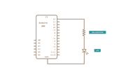
If you want to light an external LED with this sketch, you need to build this circuit, where you connect one end of the resistor to the digital pin correspondent to the LED_BUILTIN constant. Connect the long leg of the LED (the positive leg, called the anode) to the other end of the resistor. Connect the short leg of the LED (the negative leg, called the cathode) to the GND. In the diagram below we show an UNO board that has D13 as the LED_BUILTIN value.
The value of the resistor in series with the LED may be of a different value than 220 ohms; the LED will light up also with values up to 1K ohm.
Schematic
Code
After you build the circuit plug your Arduino board into your computer, start the Arduino Software (IDE) and enter the code below. You may also load it from the menu File/Examples/01.Basics/Blink . The first thing you do is to initialize LED_BUILTIN pin as an output pin with the line
pinMode(LED_BUILTIN, OUTPUT);In the main loop, you turn the LED on with the line:
digitalWrite(LED_BUILTIN, HIGH);This supplies 5 volts to the LED anode. That creates a voltage difference across the pins of the LED, and lights it up. Then you turn it off with the line:
digitalWrite(LED_BUILTIN, LOW);That takes the LED_BUILTIN pin back to 0 volts, and turns the LED off. In between the on and the off, you want enough time for a person to see the change, so the
delay()commands tell the board to do nothing for 1000 milliseconds, or one second. When you use the
delay()command, nothing else happens for that amount of time. Once you’ve understood the basic examples, check out the BlinkWithoutDelay example to learn how to create a delay while doing other things.
Once you’ve understood this example, check out the DigitalReadSerial example to learn how read a switch connected to the board.
See Also
Learn more
You can find more basic tutorials in the built-in examples section.
You can also explore the language reference, a detailed collection of the Arduino programming language.
Last revision 2015/07/28 by SM
Fading a LED
This example demonstrates the use of the analogWrite() function in fading an LED off and on. AnalogWrite uses pulse width modulation (PWM), turning a digital pin on and off very quickly with different ratio between on and off, to create a fading effect.
Hardware Required
- Arduino board
- LED
- 220 ohm resistor
- hook-up wires
- breadboard
Circuit
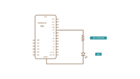
Connect the anode (the longer, positive leg) of your LED to digital output pin 9 on your board through a 220 ohm resistor. Connect the cathode (the shorter, negative leg) directly to ground.

Schematic
Code
After declaring pin 9 to be your
ledPinthere is nothing to do in the
setup()function of your code.
analogWrite()function that you will be using in the main loop of your code requires two arguments: One telling the function which pin to write to, and one indicating what PWM value to write.
In order to fade your LED off and on, gradually increase your PWM value from 0 (all the way off) to 255 (all the way on), and then back to 0 once again to complete the cycle. In the sketch below, the PWM value is set using a variable called
brightnessEach time through the loop, it increases by the value of the variable
fadeAmountbrightnessis at either extreme of its value (either 0 or 255), then
fadeAmountis changed to its negative. In other words, if
fadeAmountis 5, then it is set to -5. If it’s -5, then it’s set to 5. The next time through the loop, this change causes
brightnessto change direction as well.
analogWrite()can change the PWM value very fast, so the delay at the end of the sketch controls the speed of the fade. Try changing the value of the delay and see how it changes the fading effect.
Learn more
You can find more basic tutorials in the built-in examples section.
You can also explore the language reference, a detailed collection of the Arduino programming language.
Last revision 2015/07/29 by SM
Create a LED Dimmer
This example shows how to send data from a personal computer to an Arduino board to control the brightness of an LED. The data is sent in individual bytes, each of which ranges in value from 0 to 255. The sketch reads these bytes and uses them to set the brightness of the LED.
You can send bytes to the board from any software that can access the computer serial port. Examples for Processing and Max/MSP version 5 are shown below.
Hardware Required
- Arduino Board
- LED
- 220 ohm resistor
Software Required
- Processing or
- Max/MSP version 5
Circuit
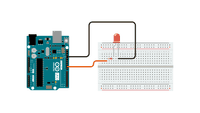
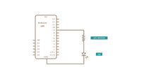
Connect the 220 ohm current limiting resistor to digital pin 9, with an LED in series. The long, positive leg (the anode) of the LED should be connected to the output from the resistor, with the shorter, negative leg (the cathode) connected to ground.
Schematic
Code
1/*2 3 Dimmer4 5 Demonstrates sending data from the computer to the Arduino board, in this case6 7 to control the brightness of an LED. The data is sent in individual bytes,8 9 each of which ranges from 0 to 255. Arduino reads these bytes and uses them to10 11 set the brightness of the LED.12 13 The circuit:14 15 - LED attached from digital pin 9 to ground.16 17 - Serial connection to Processing, Max/MSP, or another serial application18 19 created 200620 21 by David A. Mellis22 23 modified 30 Aug 201124 25 by Tom Igoe and Scott Fitzgerald26 27 This example code is in the public domain.28 29 https://www.arduino.cc/en/Tutorial/Dimmer30 31*/ 32 33const int ledPin = 9; // the pin that the LED is attached to 34 35 void setup() 36 37 // initialize the serial communication: 38 39 Serial.begin(9600); 40 41 // initialize the ledPin as an output: 42 43 pinMode(ledPin, OUTPUT); 44 > 45 46 void loop() 47 48 byte brightness; 49 50 // check if data has been sent from the computer: 51 52 if (Serial.available()) 53 54 // read the most recent byte (which will be from 0 to 255): 55 56 brightness = Serial.read(); 57 58 // set the brightness of the LED: 59 60 analogWrite(ledPin, brightness); 61 62 > 63 > 64 65 /* Processing code for this example66 67 // Dimmer - sends bytes over a serial port68 69 // by David A. Mellis70 71 // This example code is in the public domain.72 73 import processing.serial.*;74 75 Serial port;76 77 void setup() 78 79 size(256, 150);80 81 println("Available serial ports:");82 83 // if using Processing 2.1 or later, use Serial.printArray()84 85 println(Serial.list());86 87 // Uses the first port in this list (number 0). Change this to select the port88 89 // corresponding to your Arduino board. The last parameter (e.g. 9600) is the90 91 // speed of the communication. It has to correspond to the value passed to92 93 // Serial.begin() in your Arduino sketch.94 95 port = new Serial(this, Serial.list()[0], 9600);96 97 // If you know the name of the port used by the Arduino board, you can specify98 99 // it directly like this.100 101 //port = new Serial(this, "COM1", 9600);102 103 >104 105 void draw() 106 107 // draw a gradient from black to white108 109 for (int i = 0; i < 256; i++) 110 111 stroke(i);112 113 line(i, 0, i, 150);114 115 >116 117 // write the current X-position of the mouse to the serial port as118 119 // a single byte120 121 port.write(mouseX);122 123 >124 125*/ 126 127 /* Max/MSP v5 patch for this example128 129----------begin_max5_patcher----------130 1311008.3ocuXszaiaCD9r8uhA5rqAeHIa0aAMaAVf1S6hdoYQAsDiL6JQZHQ2M132 133YWr+2KeX4vjnjXKKkKhhiGQ9MeyCNz+X9rnMp63sQvuB+MLa1OlOalSjUvrC134 135ymEUytKuh05TKJWUWyk5nE9eSyuS6jesvHu4F4MxOuUzB6X57sPKWVzBLXiP136 137xZtGj6q2vafaaT0.BzJfjj.p8ZPukazsQvpfcpFs8mXR3plh8BoBxURIOWyK138 139rxspZ0YI.eTCEh5Vqp+wGtFXZMKe6CZc3yWZwTdCmYW.BBkdiby8v0r+ST.W140 141sD9SdUkn8FYspPbqvnBNFtZWiUyLmleJWo0vuKzeuj2vpJLaWA7YiE7wREui142 143FpDFDp1KcbAFcP5sJoVxp4NB5Jq40ougIDxJt1wo3GDZHiNocKhiIExx+owv144 145AdOEAksDs.RRrOoww1Arc.9RvN2J9tamwjkcqknvAE0l+8WnjHqreNet8whK146 147z6mukIK4d+Xknv3jstvJs8EirMMhxsZIusET25jXbX8xczIl5xPVxhPcTGFu148 149xNDu9rXtUCg37g9Q8Yc+EuofIYmg8QdkPCrOnXsaHwYs3rWx9PGsO+pqueG2150 151uNQBqWFh1X7qQG+3.VHcHrfO1nyR2TlqpTM9MDsLKNCQVz6KO.+Sfc5j1Ykj152 153jzkn2jwNDRP7LVb3d9LtoWBAOnvB92Le6yRmZ4UF7YpQhiFi7A5Ka8zXhKdA154 1554r9TRGG7V4COiSbAJKdXrWNhhF0hNUh7uBa4Mba0l7JUK+omjDMwkSn95Izr156 157TOwkdp7W.oPRmNRQsiKeu4j3CkfVgt.NYPEYqMGvvJ48vIlPiyzrIuZskWIS158 159xGJPcmPiWOfLodybH3wjPbMYwlbFIMNHPHFOtLBNaLSa9sGk1TxMzCX5KTa6160 161WIH2ocxSdngM0QPqFRxyPHFsprrhGc9Gy9xoBjz0NWdR2yW9DUa2F85jG2v9162 163FgTO4Q8qiC7fzzQNpmNpsY3BrYPVJBMJQ1uVmoItRhw9NrVGO3NMNzYZ+zS7164 1653WTvTOnUydG5kHMKLqAOjTe7fN2bGSxOZDkMrBrGQ9J1gONBEy0k4gVo8qHc166 167cxmfxVihWz6a3yqY9NazzUYkua9UnynadOtogW.JfsVGRVNEbWF8I+eHtcwJ168 169+wLXqZeSdWLo+FQF6731Tva0BISKTx.cLwmgJsUTTvkg1YsnXmxDge.CDR7x170 171D6YmX6fMznaF7kdczmJXwm.XSOOrdoHhNA7GMiZYLZZR.+4lconMaJP6JOZ8172 173ftCs1YWHZI3o.sIXezX5ihMSuXzZtk3ai1mXRSczoCS32hAydeyXNEu5SHyS174 175xqZqbd3ZLdera1iPqYxOm++v7SUSz176 177-----------end_max5_patcher-----------178 179*/Processing Code
The Processing sketch in the code sample above will send bytes out the computer serial port to the board to dim the LED.
Max code
The Max/MSP patch in the code sample above looks like the image below. Copy it and paste it into a new patch window.

Learn more
You can find more basic tutorials in the built-in examples section.
You can also explore the language reference, a detailed collection of the Arduino programming language.
Last revision 2015/07/29 by SM